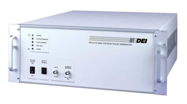
March 30th, 2022 - How Do I Slow the Rise Time of My Voltage Pulser?
The PVX series of high voltage pulsers is designed to drive small capacitive loads quickly. There is no rise/fall time adjustment, so if the rise time at the load is too fast for a particular application, a seemingly quick fix might be to place a capacitor across the pulser’s output. However, if we slow down the edges this way, we must be careful to not exceed the pulser’s average power dissipation limit.

The PVX-4110’s Maximum Dissipation Capability
Take the PVX-4110, for example. The maximum dissipation capability shown in the datasheet is 100 W.
When driving a capacitive load, power dissipation is found by:
P = C • V2 • F
where C is the total capacitance of the load, the cable, and the pulser’s output circuit in farads; V is the pulse voltage; and F is the repetition rate in pulses per second.
The PVX-4110’s internal capacitance is 50 pF, and the capacitance of RG-11 coax is 21.5 pF per foot. At maximum voltage (10000 V) and repetition rate (10 kHz), we can’t add much capacitance to the output because we reach the maximum dissipation quickly. A total capacitance of 100 pF takes us to the limit:
P = (1 • 10-10)(1 • 108)(1 • 104) = 100 W
To use this approach, we’d have to lower the voltage or the repetition rate to accommodate more output capacitance.
A better approach may be to create an RC delay by placing an external resistance between the pulser output and the capacitive load. The rise time at the load will be about three time constants, or 3RC. (R is the series resistance and C is the capacitance of the load plus the cable.)
As an example, assume we want a rise time of 200 ns. The load has a capacitance of 10 pF and it’s connected via 6 feet of coaxial cable at 21.5 pF per foot. The total capacitance is then 10 + (6 • 21.5) = 139 pF. If 3RC = 200 ns, then:
R = 200 ns/3C = (2 • 10-7)/(3 • 1.39 • 10-10) = 480 ohms
A 500 ohm resistor would provide a rise time of about 208 ns.
Choosing the Resistor
However, care should be taken in choosing the resistor. The resistor must be capable of dissipating sufficient power and may have to be enclosed for safety as well as cooled with a fan. But ordinary power resistors may still burn up easily in this kind of application. Does that always mean a higher wattage resistor is needed?
Not necessarily – it may be a high voltage issue instead of a high power issue. Very few common resistors can handle thousands of volts; most are rated at 100 V to 350 V. If the load device breaks over or conducts at some point, the voltage across it goes to zero and the entire pulse voltage appears across the resistor. It would not be surprising for a non-high-voltage-rated resistor to burn or crack under those conditions.
Also, avoid wirewound resistors unless they are noninductive; the inductance can cause a high voltage to appear across the resistor due to V = L • di/dt. The di/dt term can become quite large during pulse edges!
You can create a high voltage resistor by connecting multiple low voltage resistors in series. This technique is often used in high voltage products. For example, ten 50 ohm resistors in series is equivalent to a single 500 ohm resistor and withstands ten times the voltage. When dealing with very high voltages, be sure to allow enough space between the resistors to avoid arcing.
You can also purchase high-voltage-rated resistors from companies such as:
- Caddock Electronics, Inc.
- Ohmcraft - A Division of Exxelia USA
- Ohmite Manufacturing Company
- Vishay Intertechnology, Inc. - Resistors, Fixed - High Voltage
