

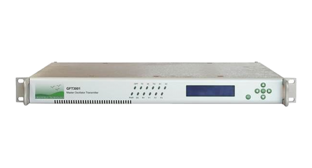

The GFT3001 synchronizes local delay generators over an optical network by generating an optical data serial data stream, as well as through master triggers and a time base. The clock reference of the GFT3001 can be external or internal. In some applications, the GFT3001 can also generate a clock to synchronize other devices (Laser, Oscillator, etc.). The GFT3001 can respond to an external hardware single-shot trigger, or generate an internal single-shot trigger. To prevent erroneous outputs, the user can stop the single-shot with a hardware-level preset.
An additional security measure is in place if the external clock reference is lost, returning the GFT3001 to a preset frequency. All parameters may be locally controlled over front panel, and remotely controlled over an Ethernet (10 / 100 Mb/s) or Internet (internal web server) interface.
The main application of the GFT3001 is in facilitating picosecond timing systems, generating severalhundred trigger pulses to equipment across the different situations encountered in large Laser timing Systems.
Overview
|
|
|
|
- Picosecond Timing System
- Laser Timing System
- Synchronous Multi-channel
- Synchrotron Timing System
Timing System
|
Distance between equipment |
>1 km (GFT3001 to local delay generator) |
|
# of Local Delay Generators |
Up to 256 |
Internal Time Base
|
Frequency |
160 MHz |
|
Accuracy / Stability |
10-9 / 0.05 ppm |
Trigger Events Source
|
Single-shot SS1, SS2 Source |
From front panel, Ethernet or Trigger input |
|
Repetitive Trigger Events |
From 3 counters. Each is programmable 1 kHz to 1/60 Hz |
Trigger Input
|
Trigger Active |
Slope positive, Threshold =+1 V, Internal load 50 Ω |
Inhibition Input
|
Inhibition Active |
Active high, Threshold =+1 V, Internal load 50 Ω |
Clock Input
|
Shape |
Sinewave or Square |
|
Threshold |
0 V, Internal 50 Ω load |
|
Level |
-3 dBm min. |
|
Frequency |
10 MHz |
Optical Data Stream Output
|
Repetition Rate |
160 Mb/s (up to 200 Mb/s as an option) |
|
Optical Power / Wavelength |
4 dBm mean / 1550 nm |
|
Rise and Fall Time |
< 1 ns |
|
Connector |
SC with shutter |
T0 Output
|
Source |
Single or Repetitive trigger |
|
Amplitude |
2, 5, to 10 V under 50 Ω |
|
Rise / Fall Time |
< 2 ns, < 5 ns |
|
RMS Jitter |
15 ps to local delay generator (T0 output) |
|
Width |
100 ns to 10 µs |
General Specifications
|
User Interface |
Local PAV, Ethernet / Internet (Web page) |
|
Size |
Rack 19’’, 1U, 300 mm |
|
Power |
90 to 240 V / 1 A |
|
Software Tools |
DLL, VI LabVIEW |
Options
|
Option 1 |
Clock Output: Sinewave, 3 dBm, 80 MHz, >-40 dBm Spectral Purity |
|
Option 2 |
Specific Clock Input frequency (10 MHz to 100 MHz) ask when ordering |
|
Option 3 |
Programmable Single-Shot sequence (repetitive, single burst, repetitive burst) |
|
Option 4 |
More repetitive triggers (up to 3 with fixed frequency) ask when ordering |
Downloadable resources such as datasheets, firmware, software, drivers and products manuals. Alternatively, you can browse resources directly by visiting our downloads page.
• Product Datasheets
• Product Firmware
• Product Software and Drivers
• Product Manuals