Researchers and system integrators, needing controls and diagnostics for their experiments and systems, are regularly forced to build from scratch or to piece together several boxes. Many hours are spent learning the idiosyncrasies of each box and how to properly couple boxes to each other. Each box has its own programming protocol. Valuable time is lost to tracking connections, taming noisy signals, adjusting timing on multiple boxes, and other aggravating chores. Now, one box will eliminate such issues. This is a great upgrade to the PSPL2600C Pulse Generator that was discontinued a few years ago.
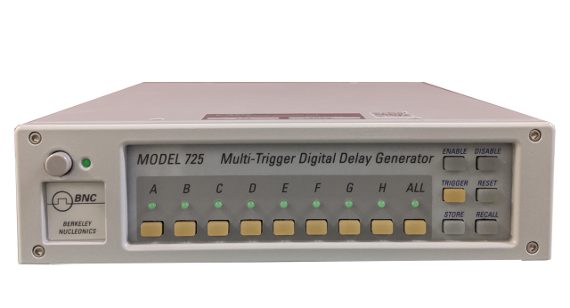
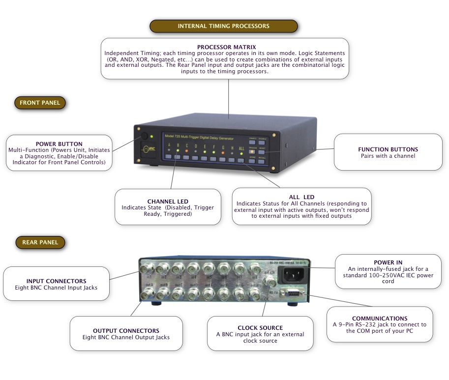
The Model 725 coordinates, integrates, and synchronizes complicated setups, simply, reliably, and affordably. Featuring eight timing channels with programmable logic, unique timing modes, and 10 ns resolution, the Model 725 outperforms a rack full of instruments, specialized boxes, filters, and cables. Inputs can be logic signals, switches, transducers, interlocks, computer commands, and gauges. The Model 725 can be programmed and controlled easily via LabVIEW or Windows. It contains sophisticated logic, gating, and filtering. It has eight inputs, eight outputs and eight separate timers.
The Model 725 logic is engineered for fast data throughput (11 ns) and minimal throughput spread (~1 ns). It would be difficult to match this performance with external cabling and hard-wired logic.
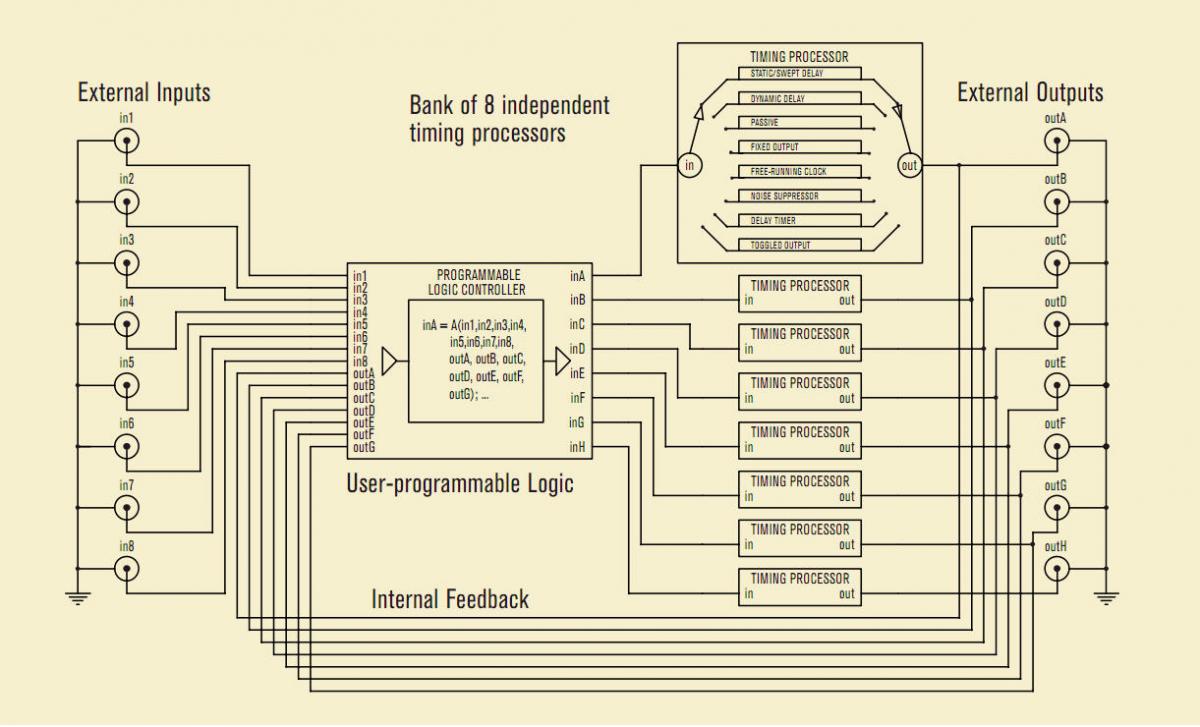
Timing Diagram for Model 725 shows Independant Timers for Each Channel, Interrelated
Overview
Quick Specs |
Applications |
|||||||||||||||||||||||||||||||||||||||
|
|
|||||||||||||||||||||||||||||||||||||||
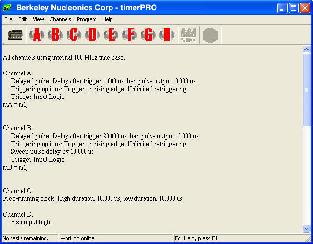
The Model 725 hardware controller can operate in stand-alone mode or via computer control. The computer control system uses its own user-friendly software, timerPRO or LabVIEW,™ both tested and proven in many experiments. timerPRO makes it easy to create sophisticated control schemes from your PC. With the Model 725 linked to your computer, you will quickly program, refine, and expand experiments. Using stand-alone mode, you can store and recall up to 64 complete settings, then trigger and monitor an experiment from the Model 725’s front panel. You will have the flexibility to design experiments offline, then to embed the controller in your test environment for “set and forget” operation. The firmware in the Model 725 is field upgradeable, allowing access to new timing modes and capabilities as they become available. timerPRO’s opening window summarizes the settings and lets you configure them.
Precision Digital Delay Generators, such as the BNC 500 series pulse/delay generators uses a single or dual trigger with a common clock to synchronize multiple events. It cannot be re-triggered until the completion of the longest timed event. The Model 725 addresses a matrix of timing issues with eight triggers, eight timers and eight outputs. The triggering of each of these timers is independent of the other timers. The triggers can be logical combinations of inputs and outputs – AND’s, OR’s, XOR’s and Negated. Also any number of timers can be triggered together to function as a traditional multi-channel digital delay generator with sub-s timing.
Fluid dynamics:
In a two-pulse experiment, two lasers were fired in rapid succession to illuminate and capture successive snapshots of a high speed fluid flow. The Model 725 handled all aspects of the experiment, from warming up the lasers to precisely timing the nanosecond- scale pulses. Using the Model 725’s onboard logic and software interface, the experimenters implemented special “alignment” and “calibration” modes for preparing the experiment and “laser ready” interlocks for safety.
High speed gas flow:
A combustion-driven shock tube was used to study high speed gas flows. The Model 725 was the heart of the experiment, taking charge of ignition, pressure sensing, detonation, laser timing, data acquisition and more complex, interrelated timing sequences were orchestrated on the PC using the virtual front panel software.
The experiment inputs: Control panel switches, pressure transducers, accelerometers, ionization gauges, safety interlock, computer commands. The experiment outputs: Shutter, Camera, Laser Flashlamp, Laser Q-Switch, Data Acquisition, Oscilloscope, Diaphragm Burster, Igniter.
TIMING PROCESSOR
| PROPERTY | 725 | 725B | NOTES |
| Trigger-pulse Delay (min/max) | 50 ns / 1370 s | 12.5 ns / 859 s | Delays over 20 s have 640 ns timing resolution |
| Trigger-pulse Duration (min / max) | 7.7 µs / 1370 s | 0.75 µs / 859 s | 725B 10ns min in pulse-stretch mode |
| Delay Resolution | 10 ns | 3.125 ns | |
| Duration Resolution | 10 ns | 3.125 ns | |
| Delay Jitter from Synchronous Source (max) | 10 ns | 3.125 ns | |
| Delay Jitter from Internal Source (typ/max) | 50ps / 200ps | 70ps / 200 ps | |
| Absolute Timing Accuracy (typ/max) | <0.0001% / 0.01 | At Normal Operating Range 0 to 50°C | |
| Internal Timing (min/max) | 1.5625 MHz / 320 MHz | 0.625 MHz / 320 MHz | |
| External Timing (min/max) | 1 MHz / 100MHz | ||
| External Trigger Pulse Duration | 50 ns | ||
LOGIC PROCESSOR
| PROPERTY | MIN | MAX | TYP |
|---|---|---|---|
| Inputs | - | - | 8 external 7 internal |
| Outputs | - | - | 8 internal (to timing processors) |
| Throughput Delay | - | 11 ns | 10 ns |
ELECTRICAL CHARACTERISTICS
| PROPERTY | MIN | MAX | TYPICAL | NOTES | |
| Input Impedance | - | - | 4.7kΩ | DC | |
| Input Capacitance | - | - | 20 pF | ||
| Output Voltage Levels | |||||
| Logic High | 3.5 V | 4.9 V | 4.5 V | into 1kΩ load (TTL-compatible) | |
| LogicLow | 0.0 V | 0.2 V | 0.1 V | ||
| Output Source/Current | |||||
| Logic High | 32 mA | - | 50 mA | Short-circuit current | |
| Logic Low | 64 mA | - | 80 mA | Short-circuit current | |
| Output Rise Time | - | - | 10 ns | 1kΩload | |
| Input/Output Voltage Protection | -30 V | +30 V | - | ||
| Power and Communication | |||||
| Power Requirements | 100-250 VAC 50-60 Hz / 0.5 Amps | ||||
| Communication | Standard RS-232 interface 38400 Baud, 1 Stop Bit, No Parity, RTS/CTS (hardware) flow control DE-9F Connector |
||||
| Host PC and Software | Windows OS Timer Pro Software (included) LabView Driver (Available to Download) |
||||
| Certification | CE | ||||
| Physical and Environmental | |||||
| Dimension (L x W x H) | 9.5" x 8.2" x 2.4" (242mm x 208mm x 60mm) | Enamel-coated anti RFI steel Enclosure Electrostatically Shield | |||
| Shipping Dimensions | 18x12x9" |
| Shipping Weight | 10 lbs |
Downloadable resources such as datasheets, firmware, software, drivers and products manuals. Alternatively, you can browse resources directly by visiting our downloads page.
• Product Datasheets
• Product Firmware
• Product Software and Drivers
• Product Manuals
Price List
Price lists are available to our registered users. To view pricing for this and other products, please log in or create a free account.