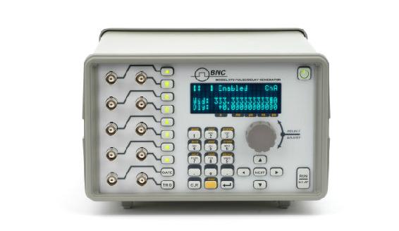


Berkeley Nucleonics’ 500 series Delay Generators offer industry-leading precision in a multitude of user-friendly form factors. Our Model 575 offers, 2, 4, or, 8 independent outputs that are designed to provide cutting edge and cost-effective solutions. Our DDG’s generate and synchronize multiple pulses for a wide range of applications. The delay and pulse width for each channel are independent and digitally controlled which makes the instrument ideal for situations that require synchronizing several different events, all making the 575 one of the most flexible delay generator on the market with a host of optical/electrical inputs and outputs.
Overview
Quick Specs |
Service Features |
|
|
Custom Output Modes
Custom Modules such as the TZ-50 give users an expand list of capabilities with the Model 575. One example is our TZ-50 option, which allows customers a TTL signal into 50 ohms expanded.
Negative Delay
Note that Negative Delay cannot trigger a channel before your initial trigger. It is intended to complement the channel referencing option.
45V rise-time into 50 Ω, <2 ns
45V rise-time into Hi-Z, < 9 ns
***Due to the power consumption and heat restrictions, a maximum of four AT45 channels can be added on a single unit***
INTERNAL RATE GENERATOR
| Rep Rate | 0.001 Hz to 10.000 MHz (1000 s - 100 ns) |
| Resolution | 5ns |
| Accuracy | Same as timebase |
| Jitter | 50 ps |
| Setting | 1 cycle |
| Burst Mode | 1 to 10,000,000 |
EXTERNAL GATE INPUT (Standard)
| Number | 0 or 1 |
| Threshold | 0.2 to 15 VDC |
| Max Input Voltage | 60 V Peak |
| Resolution | 10 mV |
| Polarity | Active High/Active Low |
| Function | Pulse Inhibit or Output Inhibit |
| Channel Behavior | Global w/ Individual Channel Enables |
EXTERNAL TRIGGER INPUT (Standard)
| Number | 1 or 2 |
| Rate | DC to 1/(200ns + longest delay) maximum of 5MHz |
| Threshold | 0.2 to 15 VDC |
| Max Input Voltage | 60 V Peak |
| Resolution | 10 mV |
| Slope | Rising or Falling |
| Impedance | 1 M ohm + 40 pF or 50 ohm |
| Jitter | 800 ps RMS |
| Insertion Delay | 180 ns Max |
| Minimum Trigger Pulse Width | 2 ns |
ELECTRICAL [TTL/ ADJUSTABLE] OUTPUTS (Standard)
| Number of Channels | 2, 4 or 8 Outputs |
| Output Impedance | High Impedance |
| Pulse Width Range | 10 ns - 1000 secs |
| Delay Range | 0 ns - 1000 secs |
| Delay and Pulse Width Resolution | 250 ps |
| RMS Jitter | 200 ps |
| Pulse Inhibit Delay | 120 ns |
| Output Inhibit Delay | 50ns |
| TTL Rise Time (10% - 90%) | 3 ns typical |
| Adjustable Slew Rate | 0.1 V/ns |
| Overshoot | < 100 mV + 10% of pulse amplitude |
| Levels | TTL 4 VDC into Hi-Z Adjustable amplitude, 2.0 to 20.0 VDC into Hi-Z; 10 mV resolution |
OPTICAL INPUTS (Option IL82 or IL130)
| Number | 0 or 2 |
| Wavelength | 820 nm or 1300 nm |
| Max Signal Rate | 5 Mbd |
| Max Link Distance | 1.5 km |
| Connector Type | ST |
| Resolution | 500 ps |
| Accuracy | 2 ns + .001 x delay |
| Optical Trigger | 2412 |
| Trigger Delay | < 300 ns |
| Jitter | < 15 ns |
OPTICAL OUTPUTS (Option L82 or L130)
| Number | 0, 2, 4, or 8 |
| Wavelength | 820 nm or 1300 nm |
| Max Signal Rate | 5 M Bd |
| Max Link Distance | 1.5 km |
| Connector Type | ST |
| Pulse Width Range | 10 ns - 1000 secs |
| Delay Range | 0 ns - 1000 secs |
| Resolution | 500 ps |
| Accuracy | 1 ns + .0001 x delay |
STANDARD FEATURES/ FUNCTIONS
| Communications | USB / RS232 |
| Global Gates/Triggers | 2 Global Gate/Trigger Inputs |
| Channel Gates/Triggers | Optical/Electrical available (5 ns Jitter) |
| External Clock in | 10 MHz - 100 MHz (User Selectable in discrete values) |
| External Clock out | 10 MHz - 100 MHz (User Selectable in discrete values) |
| Command Set Compatibility | Backwards Compatible |
Output Options
Option L82 or Option L130 - Optical Outputs
| Wavelength | 820 nm or 1300 nm |
| Maximum Signal Rate | 5 MBd |
| Maximum Link Dist. | 1.5 km |
| Connector Type | ST |
Option TZ50 - TTL 50 Ω Output Impedance
| TTL/CMOS Mode | |
| Output Level | 4.0 V (typical) into 50 Ω |
| Rise Time | <3 ns (2ns typical) |
| Slew Rate | 0.5 V/ns |
| Jitter - Channel to Channel | 50 ps RMS |
| Adjustable Mode | |
| Output Level | 2 V to 20 VDC into 1 kΩ or 1 V to 10 VDC into 50 Ω |
| Amplitude Resolution | 10 mV |
| Current | 200 mA typical, 400 mA (short pulses) |
| Rise Time (10% - 90%) | 15 ns (typical) @ 20V into Hi-Z (25 ns typ @ 10V into 50 Ω) |
| Slew Rate | > 0.1V/ns |
| Overshoot | < 1 V + 10% of pulse amplitude |
Option AT35 - 35V Adjustable Output
| TTL/CMOS Mode | |
| Output Level | 4.0 V (typical) into Hi-Z |
| Rise Time | <3 ns (2 ns typical) |
| Slew Rate | 0.5 V/ns |
| Jitter - Channel to Channel | 50 ps RMS |
| Adjustable Mode | |
| Output Amplitude | 5 V – 35 V into 50 Ω load at 200 Hz |
| Resolution | 10 mV |
| Rise Time (10% - 90%) | < 30 ns |
| Accuracy | 500 mV |
| Max. Frequency (Internal & External) | 4 kHz |
Option TZ35 - TTL 50 Ω Output Impedance + 35V Adjustable Output
| TTL/CMOS Mode | |
| Output Level | 4.0 V (typical) into 50 Ω |
| Rise Time | <3 ns (2 ns typical) |
| Slew Rate | 0.5 V/ns |
| Jitter - Channel to Channel | 50 ps RMS |
| Adjustable Mode | |
| Output Amplitude | 5 V – 35 V into 50 Ω load at 200 Hz |
| Resolution | 10 mV |
| Rise Time (10% - 90%) | < 30 ns |
| Accuracy | 500 mV |
| Max. Frequency (Internal & External) | 4 kHz |
Option AT45 - 45V High and Low Impedance
| Amplitude | 4 V - 45 V |
| Resolution | 20 mV |
| Accuracy | ±1.5% |
| Rise Time (10%-90%) | < 2 ns (typical) into 50 Ω / < 9 ns (typical) into Hi-Z |
| Fall Time (90%-10%) | < 9 ns (typical) into 50 Ω / < 9 ns typical into Hi-Z |
| Frequency (Internal & External) | DC – 100 kHz |
| Overshoot | < 35% Typical for Fast Rise Time |
| Polarity - Hi-Z (>10k) | Active High or Active Low |
| Polarity - (50 Ω) | Active High Only |
| Pulse Width Range - Hi-Z (>10k) | 10 ns to DC |
| Pulse Width Range - 50 Ω | 10 ns to 10 s |
| Max Current | 35 mA (Hi-Z @10 ms width) / 900 mA (50 Ω @ 10 ms width) |
| Shipping Dimensions | 18x12x9" |
| Shipping Weight | 10 lbs |
AT45 NOTE:
* Due to the power consumption and heat restrictions, a maximum of four AT45 channels can be installed on a single unit
** Deletes TTL and ADJUSTABLE mode selection and replaced by LOW and HIGH Impedance selection
System Options
| DT15 | Dual Trigger. Enable Gate Input to act as second trigger |
| COM | Extended Communications – Adds Ethernet & GPIB |
| EU | Replace North American Cord with European Cord |
Downloadable resources such as datasheets, firmware, software, drivers and products manuals. Alternatively, you can browse resources directly by visiting our downloads page.
• Product Datasheets
• Product Firmware
• Product Software and Drivers
• Product Manuals
Media
Price List
Price lists are available to our registered users. To view pricing for this and other products, please log in or create a free account.